Nifty__
Nifty__
View this project on GitHub
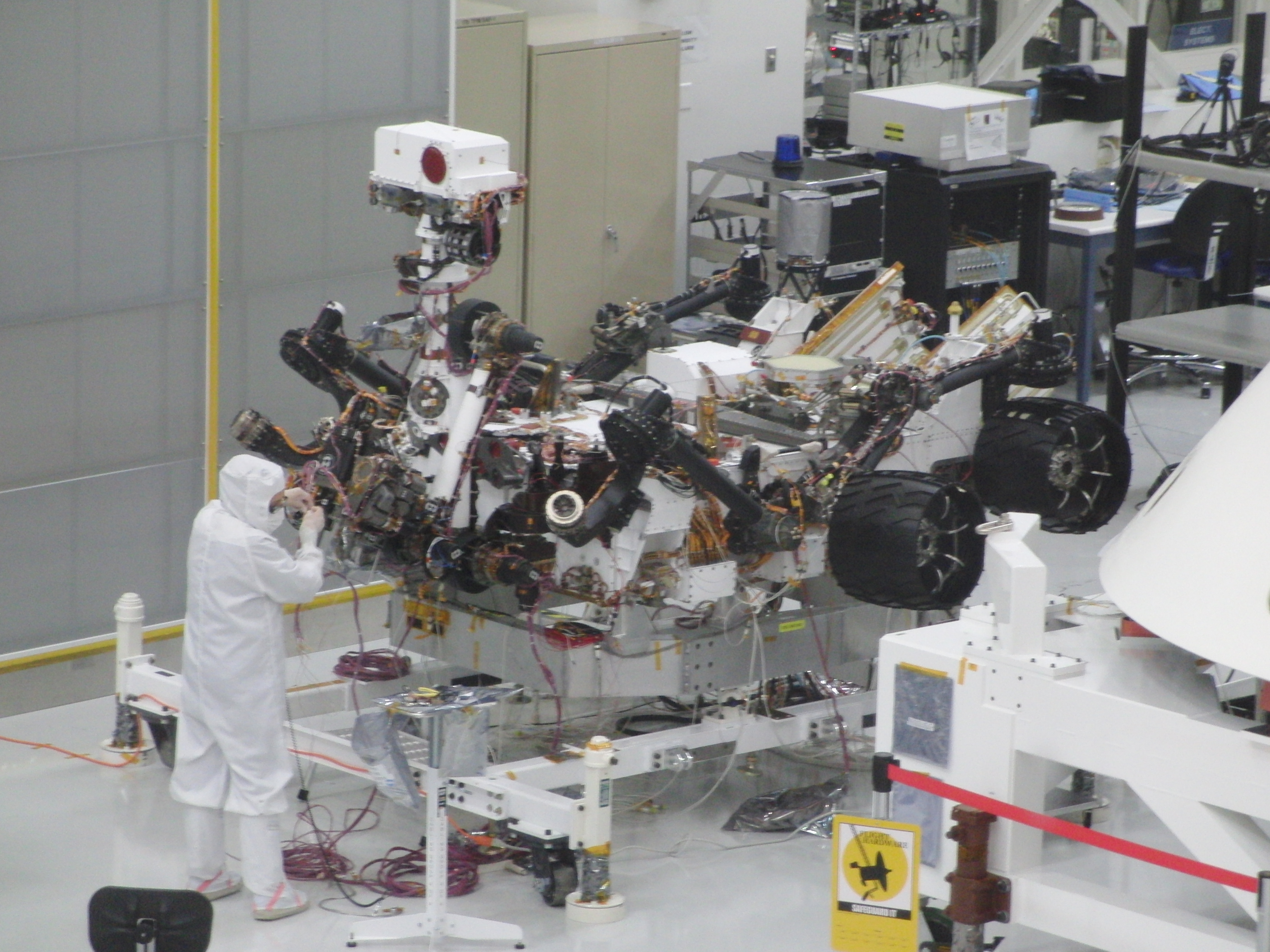
This project is a small component of the larger Instrument ShAred Artifact for Computing (ISAAC) project. ISAAC is a highly capable, highly reusable, modular, and integrated FPGA-based common instrument control and computing platform for a wide range of space-borne instrument needs as defined in the Earth Science National Research Council (NRC) Decadal Survey Report. It has applications to various NASA space missions including the recently launched Soil Moisture Active Passive (SMAP) L-band radar and Deformation, Ecosystem Structure and Dynamics of Ice (DESDynI) InSAR.
The QM-FIR digital filter core is part of the “iCore” library, which is a collection of standard and parameterized IP cores that implement common computationally-intensive instrument control and computing functions. The main objective of this project was to port the QM-FIR core to the iBoard and use the iPanel as control and display. It involved integrating different HW components and timing requirements with an existing code base in Xilinx ISE and EDK. The filter’s design and functionality was verified with simulated radar data. Extensive testing and debugging was completed with ChipScope, UART, Ethernet (UDP and TCP/IP), Wireshark, Matlab, Python, and C++.
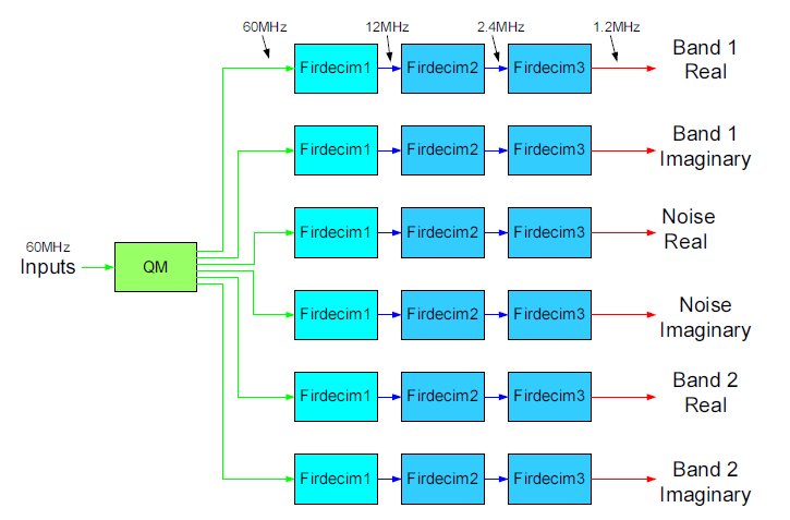
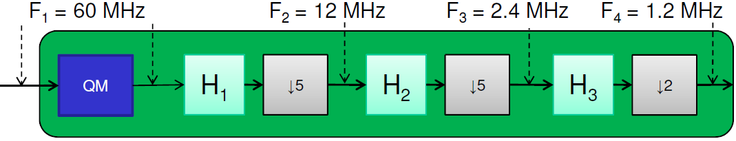
So what does the QM-FIR digital filter core actually do for telecommunication systems? The QM-FIR filter itself is a combination of two modules: a Quadrature Demodulation (QM) and a Polyphase Decimation (FIRDEC). The QM takes in a signal stream and demodulates it, moving the subbands to baseband to recover the original data. The FIRDEC uses a multi-stage decimation to turn the high-rate samples into data ready to be down-linked for further ground processing. It does a 50x decimation from a 60MHz input to a 1.2MHz output data rate.
z(t) = I(t)cos(ωct) + Q(t)sin(ωct)
This project was developed in spring of 2011 during a USRP internship at the Jet Propulsion Laboratory under the supervision of Dr. Yutao He and technical advisors, Kayla Kobayashi and Jason Zheng.
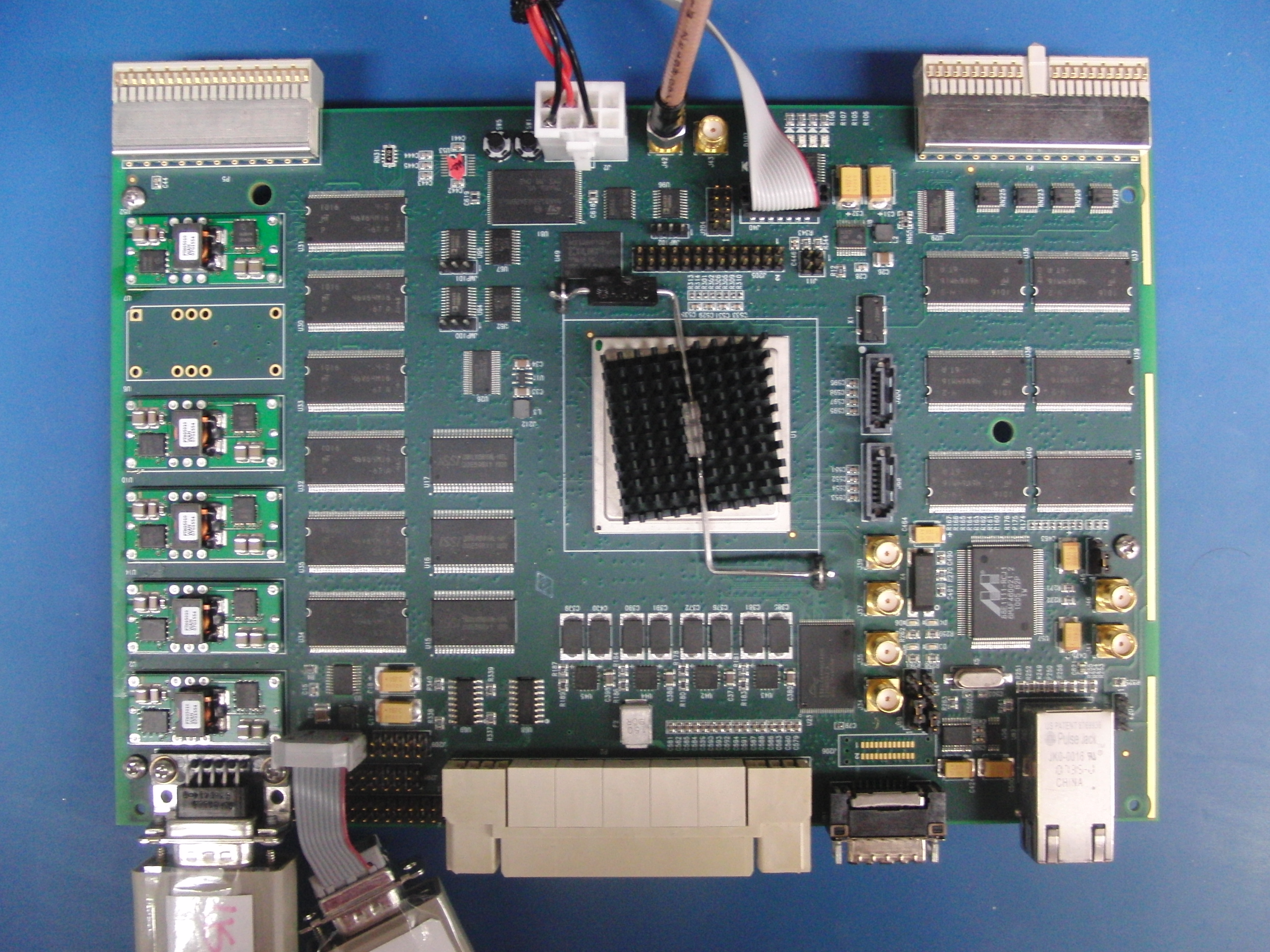
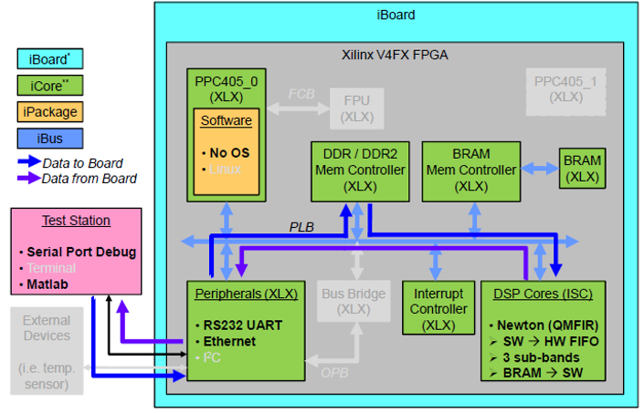
This project was implemented on the iBoard3, which contains a Xilinx Virtex-5 FPGA. Older configurations of the filter were developed for older systems using Virtex-II and Virtex-4 FPGAs. The on-board processor is the powerhouse behind the multi-stage demodulation and decimation bandpass digital filter.
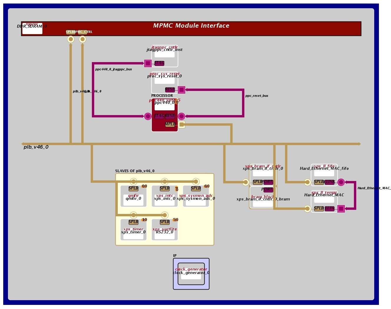
The block diagrams below shows the interface connections between the different cores of the FPGA system. A master PowerPC is interfaced to several slave devices over the processor local bus (PLB). The hardware configuration consists of memory (DDR, BRAM), Ethernet MAC, UART, interrupt controller, and a custom IP core called “qmfir,” which does the filtering.
Recall that QM-FIR conveys data by modulating a complex cosine and sine carrier signal with its real and imaginary parts, respectively, to send with two carriers on the same frequency. This is equivalent to both ASK and PSK on a single carrier. In software, the QM core is implemented using a sine/cosine lookup table and requires 6 multipliers running at 60MHz. The FIRDEC core is implemented as a three-stage polyphase decimation filter.
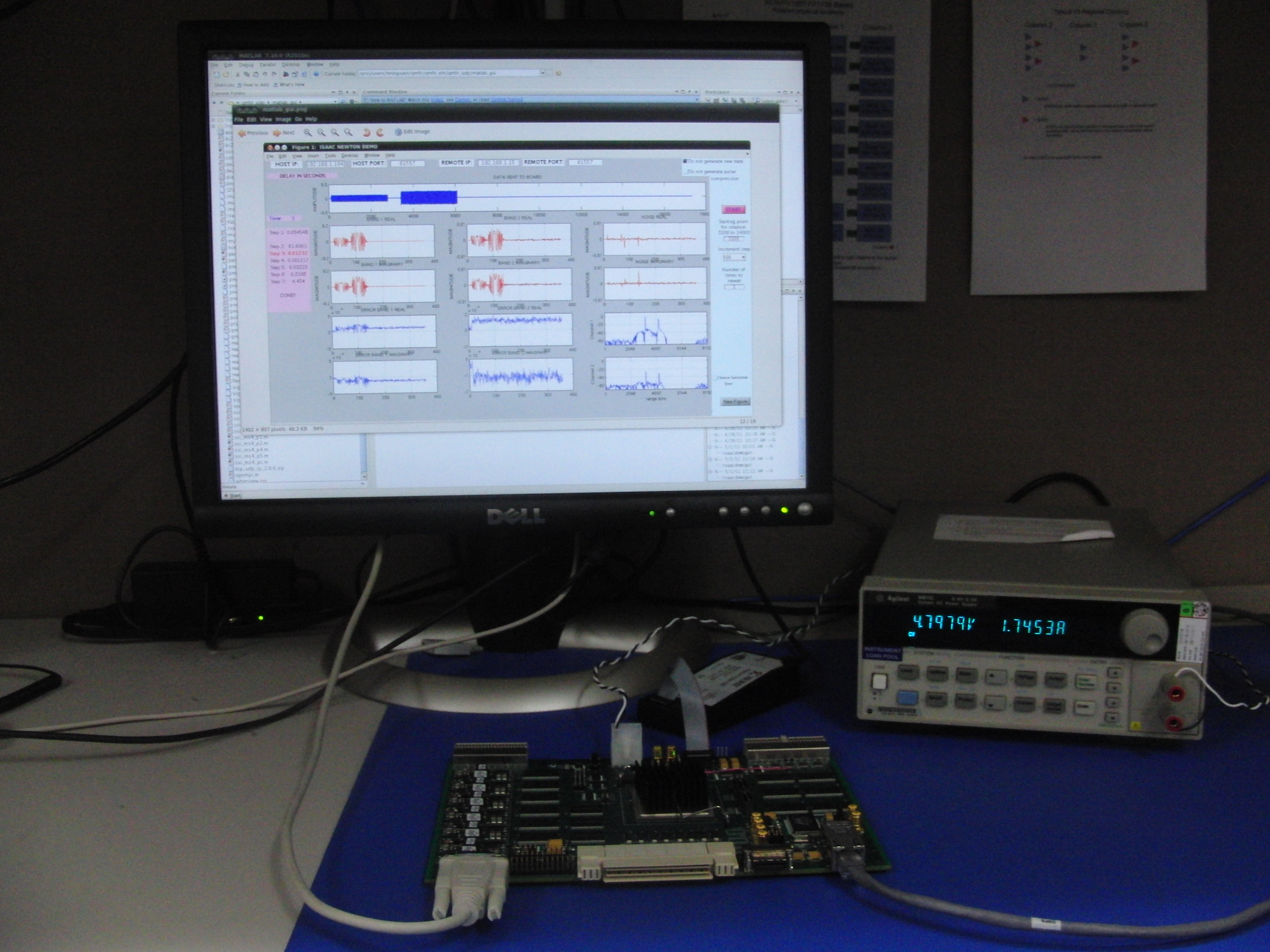
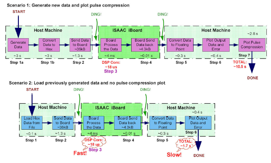
In order to verify the filter core functionality and FPGA system design, I transmitted simulated radar data streams over UART and Ethernet interfaces, and plotted the filter output in Matlab for analysis. The block diagram below illustrates a visual interpretation of the overall system data flow. It starts when Matlab generates synthetic input hex data or loads it from a file. The hex data is transferred to the iBoard where it is processed through the filter. The iBoard transfers the data back to the host machine where it is converted into floating point and can be viewed through a Matlab GUI.
The software architecture takes care of the FPGA data flow from Host Machine to iBoard to qmfir core, and back. It is comprised of Matlab, C, and Verilog source code that control the data flow in the FPGA. The Host Machine calls Matlab to generate synthetic data, transmitting it to the board over Ethernet UDP to be stored in Input BRAM. The Matlab code controls the UDP rx/tx on the host machine side, whereas the C code manages UDP on the iBoard side. Once the iBoard receives a UDP packet through a Temac FIFO, it writes it into a QMFIR writeFIFO where the Verilog code steps in. The Verilog controls the hardware and assigns the input data to be processed through various filter modules and eventually, the output is written into 3 local BRAMs. The QM-FIR digital filter core processes all of the data and stores the output in the Output BRAM. A register, called ICNT, keeps track of the number of inputs, and when that number reaches a certain watermark threshold, an interrupt is generated that triggers the iBoard to send data back to the host machine. The Host Machine grabs the data from the output BRAM, then plots it in a Matlab GUI.
Matlab → .elf → FIFO → BRAM → intr → udprecv → plot data
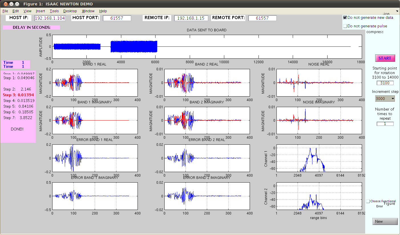
In the diagram below, the top plot shows the data that is sent to the board to be processed. This data is sampled at 60MHz. The 2nd line shows the real data from Band 1, Band 2, and noise band. The 3rd line shows the imaginary data from Band 1, Band 2, and noise band. Line 4 shows the error between the real data of the FPGA-processed data versus the data from simulation (Band 1 and Band 2 from left to right), and line 5 shows the error between the imaginary data. The last plot of lines 4 and 5 shows the pulse compression plots of the FPGA-processed data.