Nifty__
Nifty__
View this project on GitHub

Using Lego bricks and a smattering of sensors and actuators, we built a robot to efficiently navigate a maze-like course and perform search-and-rescue tasks. This robot utilized a sonar module, infrared proximity sensors, resistive contact sensors, a compass, and a web-camera to sense its environment. Based on this sensor feedback, intelligent commands could be relayed to the robot’s DC- and servo-motors to initiate locomotion and actuate the gripper. In order to successfully rescue a “victim”, several software algorithms were developed to work together in tandem including object recognition, vision processing, Monte-Carlo localization particle filtering, and PID control loops.
This project was developed in the fall of 2010 for USC’s Introduction to Robotics course (CSCI-445) taught by professor Laurent Itti. My team members included Suk-jin “Justin” Lee and Asif Ahmed, under the supervision of the great TA, Chin-Kai Chang.
LEGO bricks were the primary building blocks (pun intended) for this robot. It allowed us to design and re-design the mechanical structure as tasks became more complex. We could easily alter the robot’s body to improve balance and mobility, and also ensure that sensors were mounted properly. For example, the compass is mounted 12 inches above the robot to reduce EMI generated from the motors.
The robot is primarily “bi-pedal”, in that it utilizes two DC-motor-powered wheels to move laterally and perform center-point turns. A front gripper was constructed using a servo-motor to pick up “victims” and release them in designated safe areas. A variety of sensors are also mounted on the robot, which is powered completely by NiCad battery packs.
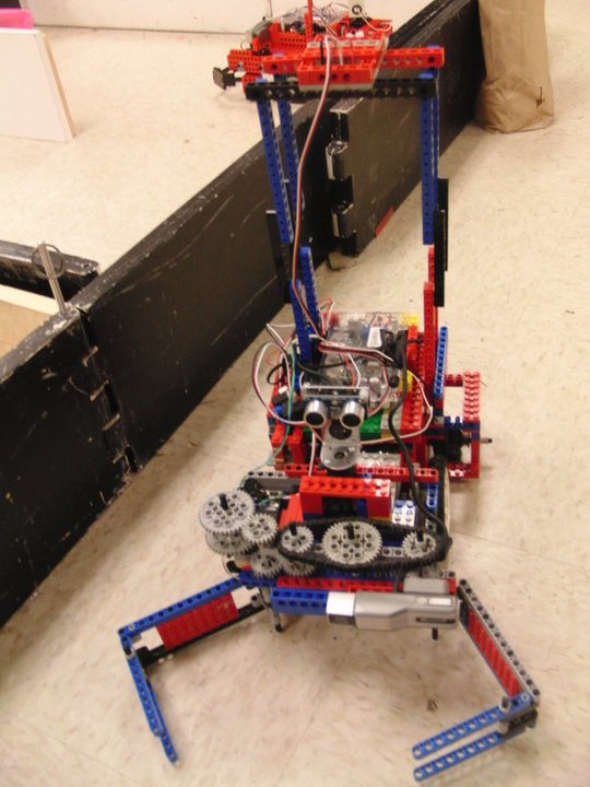
The “brains” of the robot is a custom-built NEMO Board, which utilizes a 600Mhz Gumstix Overo and ATmega 1280 microcontroller. It was built by the multi-talented engineer, Randolph Voorhies.
Project Milestones:
In order to successfully meet the project milestones, several software components were combined. My major contribution for this project was implementing the state machine and controlling the overall behavior of our robot. So, I pretty much had a hand in every part of the code for interfacing and testing/debugging all of the sensors and actuators. These include an IR sensor for wall following, sonar for moving forward and updating the particle filter, compass for (semi-accurate) turning and maintaining a forward heading, and the camera for object recognition. I also wrote the state machine that allowed the robot to find targets and plan paths to a particular destination or waypoint.
More specifically, the software components I developed were:
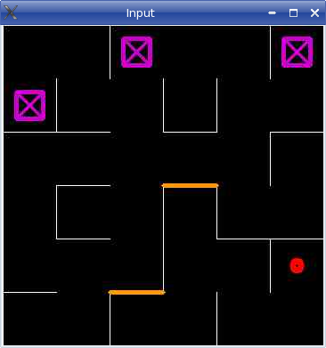
An example of the course map is shown below. The white lines represent walls. The red circle is where the robot “thinks” it’s located on the map. The purple rectangles are the designated safe areas. The pink robot and green victims could be located anywhere on the map.
The final program was quite complex, with almost 10,000 lines of code! The general state machine from /sw/final/test/Main.C is as follows:
while(1)
{
	switch(state) {
		case 0:		//search for robot, navigate map randomly
		case 1:		//found robot
		case 2:		//very close to robot
		case 3:		//parse map.txt, initialize particle filter
		case 4:		//escape from orange (go to orange and then +1)
		case 5: 	//look for green target (closest unvisited)
		case 6: 	//go to closest available purple dock
		case 7: 	//found purple, release green on dock
		case 8:		//play fight song
		case 10:	//found green
		case 11:	//grab green
		case 12:	//bring green to dock
		case 13:	//release green
}
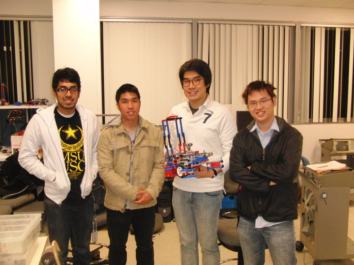 Left to right: Asif, Hieu, robot, Justin, Kai
This project gave me the opportunity to work more with programming and software control. It was nice to get a computer science perspective in robotics because now I understand why robotics is so difficult; when writing code to control a robot, things never go according to plan! You end up spending a great deal of time testing and debugging how things will transfer from a deterministic environment to the physical world. The motors were heavily dependent on the battery voltage and were not synchronized with each other. The sensors were very inaccurate; the compass readings were not divided equally by degree and the sonar did not work well over (extra) long distances. These were all challenges my group had to overcome, and we spent countless hours trying to finish the final project.
Next time, I would try to improve the speed of our robot. The path-planning algorithm now divides the map into a 13x13 grid (to account for walls) and finds its way to a desired coordinate based off this grid. However, the particle filter divides the map into centimeters (a 361x361 grid) so there is a continuous unit translation/conversion between the path-planning and particle filtering algorithms. Thus, our robot moves in small increments—once for each coordinate—and this takes a relatively long time for our robot to move to its destination because after moving, the robot must stop to take measurements for localization and navigation. While this works to accomplish the task, it is not optimal (…or fun to watch). Next time, I would try to optimize the software and remove sensor delays to improve the latency of our robot, and make it seem like the robot is moving continuously. Or perhaps somehow integrate the path-planning into the particle filter.